In the event of loss of lubrication, the transmission system is a thermal time-varying system. At this time, the transmission components inside the helicopter gear transmission system are heated up rapidly due to the friction heat, and the temperature of the entire transmission system will change with time; the structural materials and the thermal properties of the air inside the casing will also follow. Variation; radiation heat transfer that has been neglected in steady-state thermal analysis cannot be ignored under this condition; 15 nodes (lubricating oil) and 8 nodes (oil and gas mixture nodes) in a steady-state thermal network (see literature [2] ]), because the transmission system lost lubrication and was replaced by the hot air node - H node. The convective heat transfer and heat transfer in the casing are time-varying due to the time-varying effect of the thermal property parameters and the change of the heat transfer medium. Therefore, in the case of a lost helicopter gear transmission system, transient thermal analysis is required to predict the temperature field at different times.
2 Transient thermal analysis method using transient thermal analysis to solve the planetary gear transient temperature is based on the basic principle: the net heat flux of the node is equal to the increase of the energy in the node-related volume, ie qi=ΘiCpiVidTidΣ(i=1, 2, ..., n) (1) where: qi, Θi, Cpi, Vi and Ti represent the net heat flux at the i-th node, the material density, the specific heat of the material, the associated volume and temperature, respectively; Σ is the time; dTidΣ is the first The rate of temperature rise at i nodes.
Because of the radiation heat transfer, the above equation shows a series of first-order nonlinear differential equations. The boundary condition or initial condition of the differential equation is the steady-state temperature field Toi (i = 1, 2, ... n) of the system at the beginning of loss of lubrication. Solving these equations gives the system transient temperature distribution.
The numerical algorithm for solving the transient temperature field of the system is to divide the time Σ into a time series according to a certain time step, that is, Σk 1=Σk Σk(2), then the system temperature field Ti, k 1 at time 1k 1 (i= 1, 2, ..., n) can be derived from the system temperature field Ti, k (i = 1, 2, ..., n) at time Σk. That is, Ti, k 1 = Ti, k dTi, k Σ kd Σ (3) Substituting the formula (1) into the formula (3) to obtain Ti, k 1 = Ti, k qi, k Σ k (Θi, kCpi, kVi) (4) Vi is constant As long as the values ​​of qi, Ti, Θi, and Cpi at time Σk are obtained, the system temperature field distribution at time Σk 1 can be obtained.
Determination of time step in transient thermal analysis When applying the above method for transient temperature field prediction, the key issue is the reasonable determination of the time step. It is necessary to save time and make the calculation result not oscillate. If the time step is too large, there may be oscillations. In order to select a reasonable time step, the following conditions dTi, k 1dTi, k ≥ 0 (i = 1, 2, ...) should be satisfied.
n) (5) If dTi, k 1dTi, and k are negative, the above-mentioned oscillation phenomenon occurs. Deriving both sides of equation (4) for Ti, k, then dTi, k 1dTi, k = 1 (Σi, k(Θi, kCpi, kVi)) (5qi, k5Ti, k) is obtained from equation (5) 1 Σi ,k(ΘiCpi,kVi)5qi,k5Ti,k≥0, if 5qi,k5Ti,k>0, then Σi,k≥-(Θi,kCpi,kVi)(5qi,k5Ti,k) if 5qi,k5Ti,k<0 Then Σi,k≤-(Θi,kCpi,kVi)(5qi,k5Ti,k)Σi,k is the reasonable time step sought.
Based on the calculation program and calculation results of steady-state temperature field [1] and the mathematical model and analysis method of transient thermal analysis, the calculation program of transient thermal analysis of planetary transmission system is compiled. The block diagram of the program is as shown.
Determination of relevant parameters in the calculation (1) Net heat of the node qi The net heat flow qi of a node i is equal to the distribution of the power loss (heat generation) at the node Qi plus the heat QINi flowing into the node minus the outflow of the node Heat diagram 1 program block diagram flow QOUTi qi=Qi QINi-QOUTi For the planetary gear transmission system studied in this case under loss of lubrication, QINi=∑Tj-TiRjciQOUTi=∑Ti-TxRicx ∑Ti-TyRivy ∑[( Ti 273)4-(Tz 273)4]ΡΕzAz where Rjci and Ricx are conduction heat resistance; Rivy is the convective heat transfer resistance, Ρ=5.67×10⁻⁸W (m2K4) is the Boltzmann blackbody radiation constant; Εz is the surface blackness; Az is the radiation area. In the subscript, j, x, y, and z all refer to nodes that have a direct heat transfer relationship with node i.
In the case of loss of lubrication, the power loss, conduction and convection thermal resistance are calculated according to the power loss formula and the thermal resistance formula of the steady-state temperature field when lubrication is applied, but the reasons for the change of the thermal properties of the material and hot air with temperature after loss of lubrication need to be considered. .
(2) The thermal property parameters of the air inside the casing are in the condition of loss of lubrication, and the convective heat exchange medium in the casing is hot air. When calculating the convective heat transfer parameters of each node, the Prandtl number, thermal conductivity and kinematic viscosity in the formula need to be the thermal property parameters corresponding to the hot air in the casing.
Computational structure and analysis Since the density Θ(kgm3) and specific heat Cp[J(kg°C)] of the metal material are not very large with temperature, they are regarded as fixed values, and Θi, Cpi, Vi of each node are calculated. The initial value is determined according to the temperature Ti0 of each node in the steady-state temperature field in [2]. The boundary conditions here are: 1 outside the air temperature T14=25°C; 2 the air temperature inside the machine Tk 1H=T(k)H 0.02 Σ(K), the initial value of TH is 70 °C, and take the time step Σi, k=0.4. The transient temperature of each node changes with time.
After losing the lubrication, the gear frame has the highest overall temperature rise rate. When the time has passed 100s, the tooth surface temperature of the planetary gear increases by 61140 °C, and the temperature of the sun gear also rises by 33.51 °C. Since the planetary gear tooth surface participates in two meshing, the input heat is large, so the temperature rise is the fastest. And the temperature rise of the outer ring surface at the contact between the planetary wheel and the roller bearing is second only to the tooth surface temperature of the planetary gear, so the most dangerous part of the system after the loss of lubrication is the planetary gear and the roller bearing there.
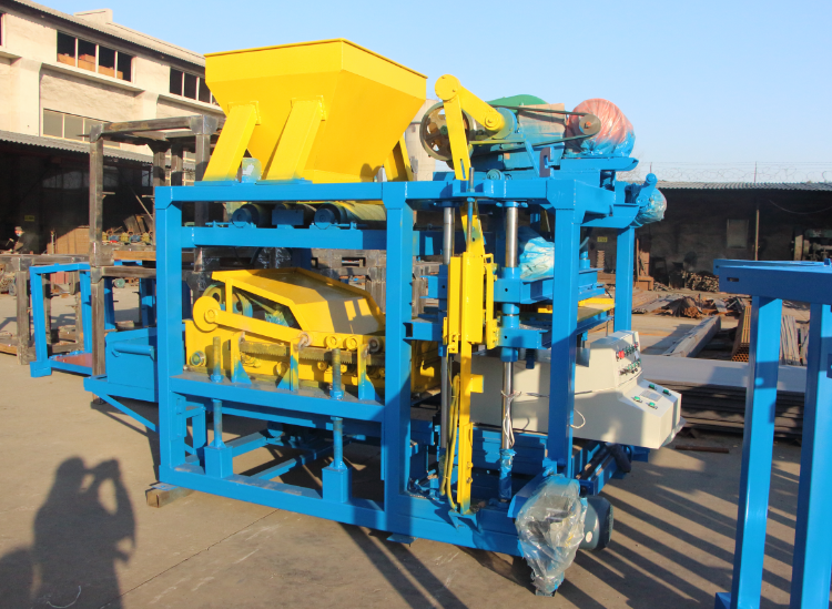
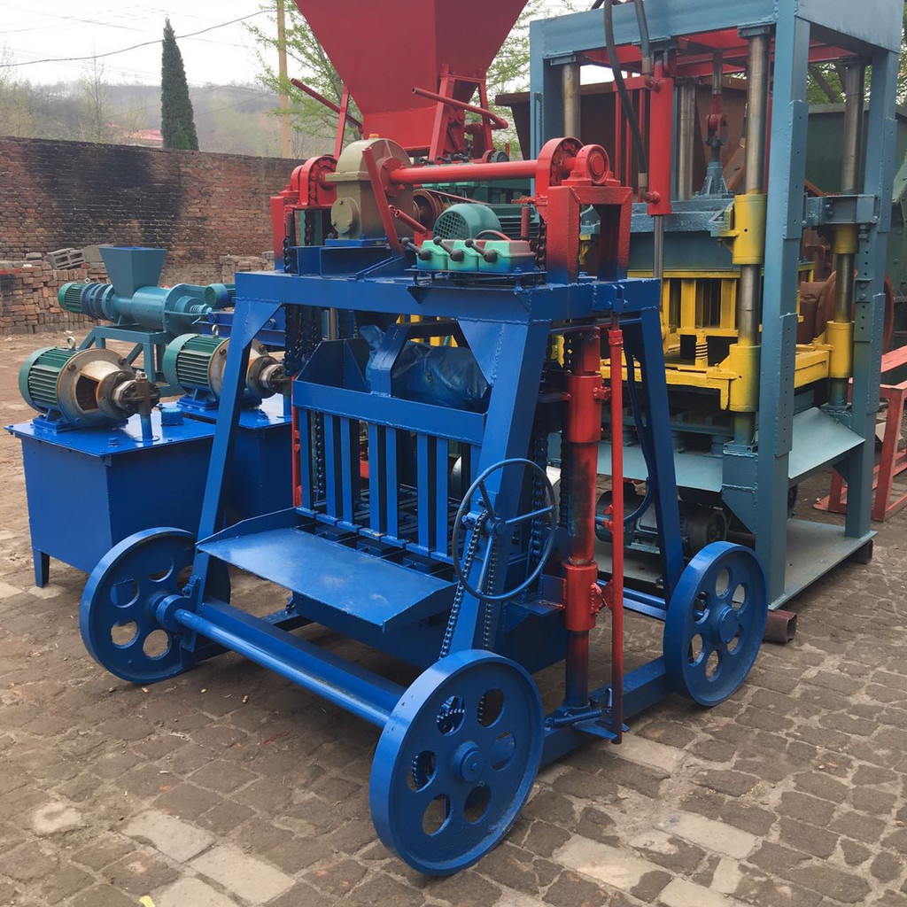
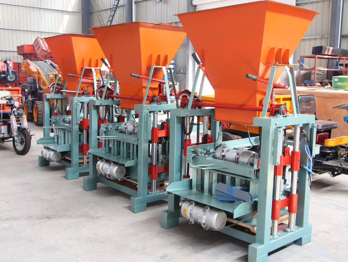
Interlock Block Machine is a very simple semi-auto machine . it is our hot sell products , very easy to operate . The investment cost is low , which is suitable for new block maker and small business runner. Just need to change the brick moulds, then you can produce various kinds of block .This Interlock Block Machine is widely used and work well in Southeast asia , Africa and South America, get many good feedback from customers.
Interlock Block Machine works with vibrating pressure to produce various hollow blocks, solid bricks, interlocking bricks, curbs, etc only by changing different moulds.


Interlock Block Machine,Block Making Machine Price,Concrete Brick Making Machine,Hollow Block Making Machine
Gongyi Xiaoyi Jinwang Machinery Factory , https://www.jinwangmachines.com