In fact, high-frequency waves are one type of ultrasound. Their standard of distinction is frequency. When the ultrasonic wave frequency is greater than 100KHz, we call it a high frequency wave. High-frequency waves use the principle of friction heating to generate a large amount of heat for welding and welding purposes. For example, we often encounter high-frequency wave plastic welding machine, which uses the enormous energy suddenly generated and welds the target object.
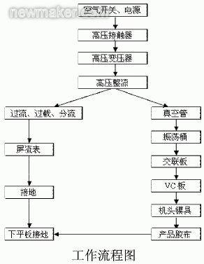
High-frequency plastic fusion splicer (Hing freguency plastic welder for short) is an electronic tube that converts electrical energy into electromagnetic waves. After being oscillated into a high-frequency electromagnetic field, high-frequency electromagnetic fields are transmitted through various transmission paths. ), PVC tape between the cooker and the ground (ie, the upper and lower poles of the high-frequency electromagnetic field), the polarization of plastic molecules polar movement and generate heat. The adhesive tape reaches the effect of welding and setting under the pressure of the mold.
The key technology of high frequency machines is to generate high frequency electromagnetic fields. The vacuum tube of the fusion splicer converts the high voltage electric energy into electromagnetic energy, and oscillates through the oscillation barrel to generate a high frequency electromagnetic field. The oscillation frequency of the oscillating barrel directly affects the strength of the output force, which in turn affects the splice quality of the product. How to measure the oscillating frequency and then adjust it to an appropriate size becomes crucial. In today's mechanization and digitization, the adjustment of the oscillation frequency of high-frequency plastic welding machines still depends on the experience of workers. This manual adjustment method often leads to defective or even failed welding of the product, and the production cost increases. Therefore, using an electronic instrument to measure the best oscillation frequency is the best solution to this problem.

Digital oscilloscopes have two methods for measuring signal frequency: software methods and hardware methods. The software method is to intercept one of the calculated average cycles in the oscilloscope's real-time stored waveform and then convert it to frequency. The frequency of the hardware method is measured by the hardware frequency meter. The hardware frequency meter calculates the trigger frequency per second as the frequency. Therefore, it is necessary to ensure that the signal is triggered during measurement. The software method and the hardware method are consistent in measuring the regular waveform measurement values, but for the irregular waveform measurement values, there will be great differences. At this time, the value measured by the software method has lost practical significance in the non-stop change, the hardware method. The measured value is more stable and closer to the average frequency, which can be used as a reference. And when measuring the oscillation frequency, its accuracy is required to be high. It needs to be accurate to 3 digits after the decimal point, the software measurement value only to 2 digits after the decimal point, and the hardware frequency meter can reach 3 or more digits. Due to the high frequency accuracy requirements, it is best to choose an oscilloscope that uses an active crystal oscillator. Since ordinary oscilloscopes are all configured passive crystal oscillators, I chose the Dingyang SDS1000CFL series of digital oscilloscopes. The 6-bit active crystal oscillator with real-time counting fully meets the requirements for measurement accuracy.
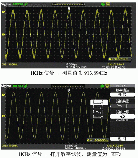
The author found in the actual measurement, signal noise interference is relatively large, resulting in hardware frequency meter display and actual wrong, which requires the oscilloscope is very good enough to filter the ability to handle noise, SDS1000CFL with its unique digital filter function (including low pass , high pass, band pass, and band stop) can effectively avoid false triggers caused by noise and make measured values ​​more accurate. The following figure shows the measured value of the interfered signal simulated by the author with 1KHz and 40mV signals. It can be seen from the figure that the digital filtered frequency measurement value is consistent with the actual signal.

The method of measuring the oscillation frequency by the inductive method can be applied to other high-frequency machines of similar working principle. This is just a simple application of the oscilloscope. With the increase of the functions and the improvement of the accuracy, the oscilloscope will gain more applications and popularity in the field of test and measurement.
Tower Crane Steel Structure, regarded as the main parts of tower crane, refers to the tower crane jib, tower crane counter jib, tower head, tower crane Telescoping Cage, tower crane turning table,tower crane pull rod, tower crane Mast Section, tower crane Fixing Angle, ect. Steel Structure is made of steel, which fits the name.
Tower crane jib is a metal lattice structure of a normally triangular section, whose main mission is to provide the crane with the necessary radius or range. It is also called a jib. Like the mast, it usually has a modular structure to facilitate its transport.
The Anchorage Frame secures the tower crane mast to a structure or framework and provides stability when the tower crane is under load or experiencing wind forces.
Machinery arm also known as the counter jib, this houses the counterweights and pulleys that balance the crane.
The hook is the main load-bearing component that hauls loads. It is attached to a trolley that allows the hook to raise and lower, as well as move towards and away from the mast.
Telescoping Cage Jacking Cage,Crane Telescoping Cage,Tower Crane Jacking Cage,Climbing Cage,Tower Crane Yoke
SHEN YANG BAOQUAN BUSINESS CO., LTD , https://www.sytoplesstowercrane.com