Abstract: In order to investigate the influence of actual installation environment and using conditions on the measurement accuracy of vortex flowmeter, a benchmark experiment was conducted on DN100 vortex flowmeter, and a total of 23 sets of real-flow experiments for a single 90° elbow and full-opening valve upstream. The experimental medium was water, and the Reynolds number ranged from 3.5 x 10⁴ to 5.3 x 10⁵. Taking the relative error of the average meter factor, the linearity of the meter factor and the repeatability as the evaluation indicators, the length of the straight section of the vortex flowmeter recommended before and after the two installation conditions is finally given: the Reynolds number is 1.0×10⁵-5.3× 10⁵ When a single elbow is used, the length of the straight section is at least 5D, and the length of the straight section is at least 3D; when the valve is fully opened, the length of the straight section is at least 5D, and the length of the straight section is at least 5D. At this time, the elbow and gate valve pair vortex flowmeter The influence of the measurement can be ignored. When the Reynolds number is between 3.5×10⁴ and 5.3×10⁵, the serious drop of the meter coefficient at the small flow point causes the vortex flowmeter to fail to achieve the measurement accuracy under the two installation conditions.
Key words: vortex flowmeter, single elbow, gate valve, meter coefficient, linearity, repetitive vortex flowmeter is a new type of velocity flowmeter based on the principle of fluid oscillation, with its insensitivity to changes in fluid properties. High reliability and high accuracy are widely used in the industrial field. Since its inception in the late 1960s, vortex flowmeters have developed rapidly. Scholars at home and abroad have conducted extensive research work on the shape of vortex generators, signal detection methods, and digital signal processing methods, and have achieved remarkable results. With the promotion and use of vortex flowmeters, the installation impact has been paid more and more attention by people. The influence of installation environment and use conditions on its measurement accuracy has become a concern.
The UK Surrey University and the British National Engineering Laboratory conducted an experimental study on the upstream installation of single 90° elbow, half-open gate valve, and two 90° elbows with different planes. The vortex flowmeter was installed in Its downstream measurement accuracy. Takamto et al. of the National Institute of Metrology, Japan, studied the measurement performance of four different shapes of vortex generators under the installation conditions of six spoilers by means of the real flow test method, and analyzed the meter factor for each type of spoiler. The relative error of the end, finally gave the length of the shortest upstream straight pipe section required to ensure the measurement accuracy of the vortex flowmeter when installing each kind of spoiler, but did not mention the length of the rear straight pipe section. In addition, China's machinery industry standard (JB/T9249-1999) also stipulates the lengths of the front and rear straight pipe sections of vortex flowmeters in the case of different spoilers, but the straight pipe sections recommended in the regulations are all relatively long. Vortex flowmeter field installation conditions can not be met. The experimental results given in foreign papers are universal, and whether they can be used directly is worth considering. At present, there are few reports on the experimental research on the installation conditions of vortex flowmeters in China. In this paper, a 100mm-caliber vortex flowmeter was used to carry out the experimental study of the influence of the single-90° elbow and the full-opening valve on the upstream. The relative error, linearity and repeatability of the average meter factor were analyzed and evaluated by experimental data. Finally, the lengths of straight pipe sections before and after the vortex flowmeter installation under the single-elbow and fully-opening valve conditions are given.
1 Experiment The experiment was performed on the water flow standard device of the Tianjin Key Laboratory of Process Parameter Detection and Control at Tianjin University. The experimental diameter was 100mm. Figure 1 shows the experimental device. The water pump continuously sends the water in the water tank to the high water tower. The water tower maintains the water pressure constant by overflowing. During the experiment, water was introduced into the experimental pipeline from the water pipe of the water tower, flowed through the standard electromagnetic flowmeter and the vortex flowmeter of the experimental prototype in sequence, and finally returned to the water tank. The flow was adjusted by adjusting the opening of the valve. The experiment was computer controlled to achieve real-time acquisition and processing of the output signals of electromagnetic flowmeters and vortex flowmeters. Water flow standard device accuracy can reach 0.1%.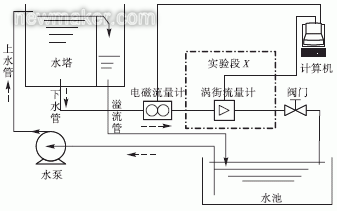
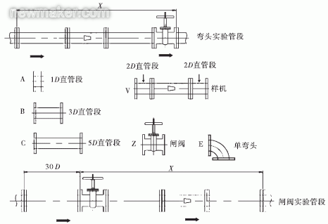
2 experimental program design Table 1 gives the experimental design of the study, a total of benchmark experiments, a single elbow upstream and full open gate valve 3 categories a total of 23 groups of real flow experiments, are shown in Figure 1 experimental section X Place. Among them, the benchmark experiment is the reference for all the blockage experiments. That is to say, the entrance of vortex flowmeter is to fully develop the turbulent flow, which is the best use condition. At this time, the length of the straight section of the vortex street flowmeter is 100D (D is the pipeline Diameter, D=100mm), and the length of the straight pipe is 10D. The experiment for single elbow and full-opening valve needs to be carried out after the device is modified. Figure 2 shows the connection of experimental pipe and assembly of elbow and gate valve.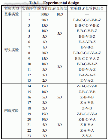
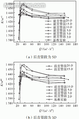
1) Relative error of the average meter factor For each flow verification point, in the ith verification time, the output pulse number of the vortex street meter is Ni, and the volume flow through the vortex flowmeter is Vi, then the flow point is The instrument coefficient for the i test is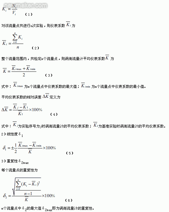 3.2 Experimental data analysis According to the widest flow range that can be achieved by the experimental device, the real-flow experiments of the single elbow and the full-opening valve are performed. Fig. 5 and Fig. 6 are the elbow experiment and the gate valve respectively. The curve with the flow rate Q changes. The figure shows only the experimental results when changing the length of the straight section before the same straight pipe section with a flow range of 24 to 150 m3/h. The flow rate at the dotted line is 28 m3/h. It should be noted that real flow experiments have found that the flow point is a demarcation point for the sudden changes in measurement performance of vortex flowmeters. When the flow rate is smaller than the flow rate, the measurement performance of the vortex flowmeter deteriorates, and the lower the flow rate, the more serious the decline of the meter coefficient. Therefore, only 24m3/h is given as an illustration in the figure. Table 2 shows the vortex flowmeter measurement performance data calculated on the basis of the evaluation indicators in Section 3.1 at both sides of the demarcation flow point.

(2) Under the same straight pipe section, with the shortening of the straight pipe section, the average meter coefficient of the vortex flowmeter gradually increases, that is, the curve gradually moves upwards.
(3) Compared with the benchmark experiment, the change in the length of the straight pipe segment has a larger impact on the small flow rate than that on the large flow rate, that is, the deviation of the meter coefficient is larger when the flow rate is small.
(4) When the current straight pipe segment is long, the straight pipe segment will have little effect on the meter factor. As the straight pipe segment is shortened, the shorter the straight pipe segment, the shorter the average meter factor deviation (see Table 2).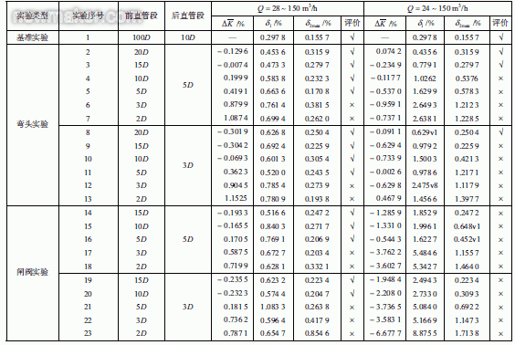
3.3 Installation and Usage Suggestion Table 2 shows the data records of 23 groups of experiments, and evaluates the data based on the evaluation indicators in Section 3.1 and the evaluation methods given in Table 3, and gives suggestions for the installation and use of vortex flowmeters. The “√†indicates that the straight pipe sections before and after the installation are appropriate; “׆indicates that the straight pipe sections before and after the installation are unsuitable, and the influence of the upstream blocking piece on the vortex flowmeter cannot be ignored.
Only for the flow rate of 28 ~ 150m3 / h gives an evaluation conclusion: According to Table 3 evaluation methods, as shown in Table 2, for the installation of a single elbow upstream, the former straight pipe segment were 2D, 3D, after the straight pipe segment was 3D, The influence of the elbow on the measurement of vortex flowmeter can not be ignored when there are 4 cases in 5D. For the upstream installation of full-opening valve, except for the combination of the above 4 kinds of straight pipe sections, the current straight pipe section is 5D, and the straight pipe section is 3D. The influence of the gate valve on the measurement of the vortex flowmeter can not be ignored.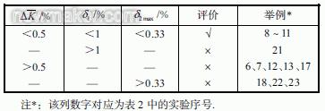
This experiment is aimed at a typical vortex flowmeter in the conventional installation angle (horizontal installation, signal converter in the top) under different straight pipe length combinations for more targeted. Experimental Reynolds number range of 3.5 × 10⁴ ~ 5.3 × 10⁵.
2) Different evaluation indexes In Takamto et al.'s study, only the relative error of the average meter factor is used as the evaluation index, and only the relative error distribution map is shown (Figure 7). The characteristics of the meter coefficient within the entire measurement range are not concerned.
In this experiment, in addition to the relative error of the average meter factor, the repeatability and linearity of the meter coefficient in the flow range were also evaluated. From Figure 5 and Figure 6 it can be seen intuitively that the change of the meter coefficient with the flow rate changes. .
3) Conclusions Different Takamto et al. concluded that when there is a single elbow spoiler in the upstream, the length of the shortest upstream straight pipe section required by the vortex flowmeter is 13D; when there is a full flow valve choke at the upstream, the vortex flowmeter The length of the shortest upstream straight section required is 5D.
The conclusion of this experiment is that when the flow rate is 28-150m3/h and there is a single elbow upstream of the vortex flowmeter, the length of the shortest upstream straight section is 5D, and the length of the downstream straight section is 3D; there is a full open valve upstream. The length of the shortest upstream straight pipe section required by the vortex flowmeter is 5D, and the length of the downstream straight pipe section is 5D. When the flow rate is less than 28m3/h, the coefficient of the vortex flowmeter is obviously reduced and it is no longer able to work normally. This shows that the spoiler has a serious impact on the performance of small flow measurement. If you want to ensure the measurement accuracy, you need to sacrifice the flow measurement range.
5 Conclusion Through the real flow experiment quantitatively studied the vortex flowmeter upstream installation single elbow and fully open the valve in the case of its measurement performance. A total of 23 real-flow experiments, including benchmark experiments, were performed. The Reynolds number ranged from 3.5×10⁴ to 5.3×10⁵. Taking the relative error of the average meter factor, the linearity of the meter coefficient and the repeatability as the evaluation indicators, the lengths of the straight pipe sections of the vortex flowmeter before and after the two installation conditions are finally given:
When the Reynolds number is 1.0×10⁵ to 5.3×10⁵, when the single elbow is used, the length of the straight section must be at least 5D, and the length of the straight section must be at least 3D. When the valve is fully opened, the length of the straight section must be at least 5D. When the length is at least 5D, the influence of the flow block on the measurement of the vortex flowmeter can be ignored.
When the Reynolds number is less than 1.0×10⁵, the measurement coefficient of the vortex flowmeter will be degraded in the entire flow range due to the serious decrease of the meter coefficient of the small flow point. When a single elbow is used, the measurement can be guaranteed only when the front straight section is 20D. Accuracy; When the valve is fully opened, the forward straight section 15D can no longer meet the accuracy requirements. Therefore, when vortex flowmeters are installed in non-ideal pipeline conditions such as elbows and gate valves, their measurement performance at low Reynolds numbers needs special attention. (
Key words: vortex flowmeter, single elbow, gate valve, meter coefficient, linearity, repetitive vortex flowmeter is a new type of velocity flowmeter based on the principle of fluid oscillation, with its insensitivity to changes in fluid properties. High reliability and high accuracy are widely used in the industrial field. Since its inception in the late 1960s, vortex flowmeters have developed rapidly. Scholars at home and abroad have conducted extensive research work on the shape of vortex generators, signal detection methods, and digital signal processing methods, and have achieved remarkable results. With the promotion and use of vortex flowmeters, the installation impact has been paid more and more attention by people. The influence of installation environment and use conditions on its measurement accuracy has become a concern.
The UK Surrey University and the British National Engineering Laboratory conducted an experimental study on the upstream installation of single 90° elbow, half-open gate valve, and two 90° elbows with different planes. The vortex flowmeter was installed in Its downstream measurement accuracy. Takamto et al. of the National Institute of Metrology, Japan, studied the measurement performance of four different shapes of vortex generators under the installation conditions of six spoilers by means of the real flow test method, and analyzed the meter factor for each type of spoiler. The relative error of the end, finally gave the length of the shortest upstream straight pipe section required to ensure the measurement accuracy of the vortex flowmeter when installing each kind of spoiler, but did not mention the length of the rear straight pipe section. In addition, China's machinery industry standard (JB/T9249-1999) also stipulates the lengths of the front and rear straight pipe sections of vortex flowmeters in the case of different spoilers, but the straight pipe sections recommended in the regulations are all relatively long. Vortex flowmeter field installation conditions can not be met. The experimental results given in foreign papers are universal, and whether they can be used directly is worth considering. At present, there are few reports on the experimental research on the installation conditions of vortex flowmeters in China. In this paper, a 100mm-caliber vortex flowmeter was used to carry out the experimental study of the influence of the single-90° elbow and the full-opening valve on the upstream. The relative error, linearity and repeatability of the average meter factor were analyzed and evaluated by experimental data. Finally, the lengths of straight pipe sections before and after the vortex flowmeter installation under the single-elbow and fully-opening valve conditions are given.
1 Experiment The experiment was performed on the water flow standard device of the Tianjin Key Laboratory of Process Parameter Detection and Control at Tianjin University. The experimental diameter was 100mm. Figure 1 shows the experimental device. The water pump continuously sends the water in the water tank to the high water tower. The water tower maintains the water pressure constant by overflowing. During the experiment, water was introduced into the experimental pipeline from the water pipe of the water tower, flowed through the standard electromagnetic flowmeter and the vortex flowmeter of the experimental prototype in sequence, and finally returned to the water tank. The flow was adjusted by adjusting the opening of the valve. The experiment was computer controlled to achieve real-time acquisition and processing of the output signals of electromagnetic flowmeters and vortex flowmeters. Water flow standard device accuracy can reach 0.1%.

Fig.1 Experimental device
The experimental prototype is Yokogawa DY100-EBLBA1-2D integrated vortex flowmeter with a diameter of 100mm. The biggest feature of this prototype is the use of a digital signal processing method based on spectrum analysis to ensure high accuracy over a wide measurement range. The measurable flow ranges from 7.5 to 248m3/h with an accuracy of up to 1%. However, due to the range of flow rates that can be provided by the experimental device, the minimum flow rate can only be 10m3/h, and the maximum flow rate can reach 200m3/h. Since the pressure loss increases after the reformation of the pipeline, the final flow rate limit can only reach about 150m3/h, so the flow rate for real flow test is 10~150m3/h. 2 experimental program design Table 1 gives the experimental design of the study, a total of benchmark experiments, a single elbow upstream and full open gate valve 3 categories a total of 23 groups of real flow experiments, are shown in Figure 1 experimental section X Place. Among them, the benchmark experiment is the reference for all the blockage experiments. That is to say, the entrance of vortex flowmeter is to fully develop the turbulent flow, which is the best use condition. At this time, the length of the straight section of the vortex street flowmeter is 100D (D is the pipeline Diameter, D=100mm), and the length of the straight pipe is 10D. The experiment for single elbow and full-opening valve needs to be carried out after the device is modified. Figure 2 shows the connection of experimental pipe and assembly of elbow and gate valve.


Figure 2 Connection of elbow and gate valve experimental pipes and components
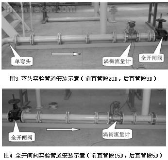
Through the combination of different pipe components to achieve different straight pipe length test. As shown in Table 1, before the elbow experiment, the straight sections were 1D, 3D, 5D, 10D, 15D and 20D. The rear straight sections were 3D and 5D. There were 12 groups of experiments. A full opening valve was installed downstream of the straight section. After the end of the straight section length. In the same way, the experiment of full-opening gate valve is carried out in 5 types of lengths of the forward straight pipe section and the lengths of the two straight straight pipe sections. The difference from the elbow test is that in order to eliminate the influence of the flow block (elbow) upstream of the gate valve on the flow field, a 30D long straight pipe section is installed upstream of the test section X. This ensures that the difference from the reference experiment is caused by the gate valve. Installation caused. Fig. 3 and Fig. 4 show the pipeline installation at the time when the straight pipe section 20D and the rear straight pipe section 3D installation conditions and the straight pipe section 15D and the rear straight pipe section 5D installation conditions before the elbow test are installed. 
3 Experimental results analysis and discussion
3.1 Experimental evaluation indicators According to the vortex flowmeter verification protocol (JJG1029-2007), when the installation meets the requirements of the full development of the straight pipe before and after the section, the measurement of vortex flowmeter measurement accuracy indicators have range ratio, linearity and so on. For the case where there is a flow block upstream and the forward and backward straight pipe segments are changed, the evaluation index includes the relative error of the average meter factor, the linearity of the meter coefficient, and the repeatability. 1) Relative error of the average meter factor For each flow verification point, in the ith verification time, the output pulse number of the vortex street meter is Ni, and the volume flow through the vortex flowmeter is Vi, then the flow point is The instrument coefficient for the i test is


Figure 5 Elbow experimental data
From Figure 5 and Figure 6 it can be seen that when the flow rate is 28-150m3/h, whether the single elbow or the gate valve, the experimental data has the following characteristics. 
Figure 6 Gate valve experimental data
(1) Under the same straight pipe section conditions, the vortex flowmeter meter coefficient gradually increases with the decrease of flow rate, but there will be a sudden drop near the lower limit flow rate. From the analysis of the working characteristics of vortex flowmeters, it is unreasonable to have a sudden drop point. The analysis may be caused by the reason that when the flow rate is small, the vortex street signal is weak and difficult to detect. In addition, interference factors such as pipeline vibration of the experimental device will make the output signal of the vortex flowmeter unstable and cause wave loss or missed detection. Although the sudden drop of the meter coefficient will cause the measurement performance of the vortex flowmeter to deteriorate, it can be seen from the data in Table 2 that the measurement performance can still be guaranteed when the front straight section is greater than or equal to 5D, ie the vortex flowmeter is still in normal condition. Working status. (2) Under the same straight pipe section, with the shortening of the straight pipe section, the average meter coefficient of the vortex flowmeter gradually increases, that is, the curve gradually moves upwards.
(3) Compared with the benchmark experiment, the change in the length of the straight pipe segment has a larger impact on the small flow rate than that on the large flow rate, that is, the deviation of the meter coefficient is larger when the flow rate is small.
(4) When the current straight pipe segment is long, the straight pipe segment will have little effect on the meter factor. As the straight pipe segment is shortened, the shorter the straight pipe segment, the shorter the average meter factor deviation (see Table 2).

Table 2 Evaluation of experimental data
For the case where the flow rate is less than 28m3/h, as shown in Fig. 5 and Fig. 6 at the flow point of 24m3/h, the shorter the forward straight pipe segment, the more serious the drop of the meter coefficient, resulting in the meter within the entire measurement range (24~150m3/h) The more serious the coefficient nonlinearity is, the worse the linearity is. In addition, the shorter the front straight pipe section, the worse the repeatability. As shown in Table 2, when the upstream flowmeter is a single elbow, only when the front straight pipe section is 20D can meet the measurement accuracy requirements. When it is a fully open valve, because the meter coefficient is nonlinear, the length of the straight pipe section in question cannot meet the measurement requirements. Since the vortex flowmeter at 24m3/h has shown poor measurement performance due to installation conditions and cannot work normally, the lower flow point conditions are not discussed in this paper. 3.3 Installation and Usage Suggestion Table 2 shows the data records of 23 groups of experiments, and evaluates the data based on the evaluation indicators in Section 3.1 and the evaluation methods given in Table 3, and gives suggestions for the installation and use of vortex flowmeters. The “√†indicates that the straight pipe sections before and after the installation are appropriate; “׆indicates that the straight pipe sections before and after the installation are unsuitable, and the influence of the upstream blocking piece on the vortex flowmeter cannot be ignored.
Only for the flow rate of 28 ~ 150m3 / h gives an evaluation conclusion: According to Table 3 evaluation methods, as shown in Table 2, for the installation of a single elbow upstream, the former straight pipe segment were 2D, 3D, after the straight pipe segment was 3D, The influence of the elbow on the measurement of vortex flowmeter can not be ignored when there are 4 cases in 5D. For the upstream installation of full-opening valve, except for the combination of the above 4 kinds of straight pipe sections, the current straight pipe section is 5D, and the straight pipe section is 3D. The influence of the gate valve on the measurement of the vortex flowmeter can not be ignored.

Table 3 Evaluation Methods
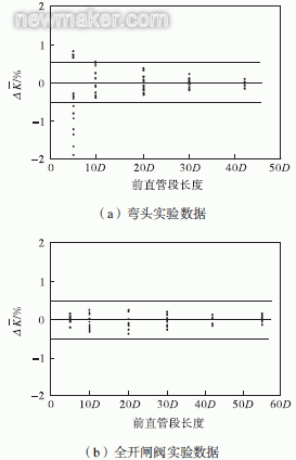
4 Comparison with relevant foreign experimental data The experimental results were compared with the experimental results of Takamto et al.'s research on the influence of vortex flowmeter installation. Figure 7 shows the vortex flowmeter at the elbow and fully open. The experimental results of the downstream of the gate valve show that the horizontal axis is the length of the straight section of the vortex flowmeter, the pipe diameter D is the minimum unit, and the vertical axis is the relative error of the average meter factor. 
Figure 7 Vortex flowmeter installation conditions affect the experimental data
1) Study contents Different Takamto et al. studied the influence of four kinds of vortex generator vortex flowmeters at two installation angles and two Reynolds number front straight pipe sections. The results shown in Figure 7 include a variety of factors. Overview. The two Reynolds numbers are 3.0 x 10⁵ and 7.0 x 10⁶, respectively. This experiment is aimed at a typical vortex flowmeter in the conventional installation angle (horizontal installation, signal converter in the top) under different straight pipe length combinations for more targeted. Experimental Reynolds number range of 3.5 × 10⁴ ~ 5.3 × 10⁵.
2) Different evaluation indexes In Takamto et al.'s study, only the relative error of the average meter factor is used as the evaluation index, and only the relative error distribution map is shown (Figure 7). The characteristics of the meter coefficient within the entire measurement range are not concerned.
In this experiment, in addition to the relative error of the average meter factor, the repeatability and linearity of the meter coefficient in the flow range were also evaluated. From Figure 5 and Figure 6 it can be seen intuitively that the change of the meter coefficient with the flow rate changes. .
3) Conclusions Different Takamto et al. concluded that when there is a single elbow spoiler in the upstream, the length of the shortest upstream straight pipe section required by the vortex flowmeter is 13D; when there is a full flow valve choke at the upstream, the vortex flowmeter The length of the shortest upstream straight section required is 5D.
The conclusion of this experiment is that when the flow rate is 28-150m3/h and there is a single elbow upstream of the vortex flowmeter, the length of the shortest upstream straight section is 5D, and the length of the downstream straight section is 3D; there is a full open valve upstream. The length of the shortest upstream straight pipe section required by the vortex flowmeter is 5D, and the length of the downstream straight pipe section is 5D. When the flow rate is less than 28m3/h, the coefficient of the vortex flowmeter is obviously reduced and it is no longer able to work normally. This shows that the spoiler has a serious impact on the performance of small flow measurement. If you want to ensure the measurement accuracy, you need to sacrifice the flow measurement range.
5 Conclusion Through the real flow experiment quantitatively studied the vortex flowmeter upstream installation single elbow and fully open the valve in the case of its measurement performance. A total of 23 real-flow experiments, including benchmark experiments, were performed. The Reynolds number ranged from 3.5×10⁴ to 5.3×10⁵. Taking the relative error of the average meter factor, the linearity of the meter coefficient and the repeatability as the evaluation indicators, the lengths of the straight pipe sections of the vortex flowmeter before and after the two installation conditions are finally given:
When the Reynolds number is 1.0×10⁵ to 5.3×10⁵, when the single elbow is used, the length of the straight section must be at least 5D, and the length of the straight section must be at least 3D. When the valve is fully opened, the length of the straight section must be at least 5D. When the length is at least 5D, the influence of the flow block on the measurement of the vortex flowmeter can be ignored.
When the Reynolds number is less than 1.0×10⁵, the measurement coefficient of the vortex flowmeter will be degraded in the entire flow range due to the serious decrease of the meter coefficient of the small flow point. When a single elbow is used, the measurement can be guaranteed only when the front straight section is 20D. Accuracy; When the valve is fully opened, the forward straight section 15D can no longer meet the accuracy requirements. Therefore, when vortex flowmeters are installed in non-ideal pipeline conditions such as elbows and gate valves, their measurement performance at low Reynolds numbers needs special attention. (
Plastic Sausage Casing,Sausage With Plastic Casing,Sausage In Plastic Wrap,Chorizo Plastic Casing
Hebei Yintop Technology Co.ltd , https://www.yintoptech.com